Daikin
Contents
Setting Indoor Group Address
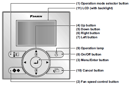
Indoor Group Address is required for proper CoolMasterNet operation. Without Group Address Indoor unit is not visible and can not be controlled by CoolMasterNet. Group Address is set with wired remote controller. Here is a simple sequence of operations for Daikin BRCE61 wired remote controller to set Group Address.
- Press and hold Cancel button for a few seconds
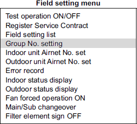
- Scroll down to Group No. setting function and press Menu/Enter button
- Program Group Address and then press Menu/Enter to save address
Remember if Indoor unit can not see a CoolMasterNet you won't have the Group Address menu option. So make sure the CoolMasterNet is wired to F1 F2 HVAC line and powered.
Reading Thermostat ambient temperature instead of return air
CoolMasterNet will read ambient temperature measured by Thermostat - local wired controller (like BRC1E72) if following field settings had being done on Thermostat:
Setting 10-2 = 03 - Only the thermostat thermistor will be utilized by Indoor unit.
Setting 10-5 = 02 - Room temperature value reported to CoolMasterNet by Indoor is taken from Thermostat
KRP928A2S Auto Mode Control
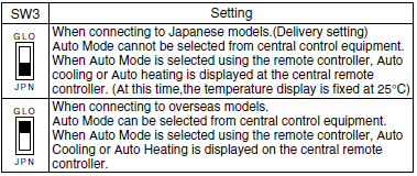
To enable proper Auto Mode control from CoolMasterNet of the Indoor Unit connected via KRP928A2S adapter, make sure to configure SW3 switch to GLO position:

Daikin Self-diagnostic Malfunction (Error) Codes
| I n d o o r U n i t |
Malfunction
Code |
Problem
Description |
Supposed
Causes |
Models | ||||||
|---|---|---|---|---|---|---|---|---|---|---|
| RA | Sky Air |
VRV | Pac kage |
HRV | Chil ler |
Fan Coil | ||||
| A0 | External protection device activated | External protection device connected to the terminal strip T1-T2 of indoor unit is activated | V | V | V | |||||
| A1 | Malfunction of indoor unit PCB | Defective indoor unit PCB External factor (Noise etc.) |
V | V | V | V | V | V | ||
| A3 | Drain Level Control System Abnormality | Drain clogging, upward slope, etc Defective drain pump Defective float switch or short circuit connector |
V | V | V | V | V | |||
| A4 | Malfunction of freezing protection | Shortage of water volume Low water temperature setting Defective water temperature thermistor |
V | V | V | V | V | V | ||
| A5 | High pressure control in heating, freeze-up protection control in cooling | Clogged air filter of indoor unit and short circuit Defect of indoor unit heat exchanger thermistor |
V | V | V | V | ||||
| A6 | Malfunction of fan motor | Broken wires in, short circuit of, or disconnection of connectors from the fan motor harness Defective fan motor Defective indoor unit PCB |
V | V | V | V | V | |||
| A7 | Malfunction of swing flap motor | Defective swing fl ap motor Defective indoor unit PCB Defective connection cable Defective airflow direction adjusting fl ap-cam |
V | V | ||||||
| A8 | Malfunction of power supply or AC input overcurrent | Defective power supply voltage Defective connection on signal line Defective wiring |
V | V | V | |||||
| A9 | Malfunction of electronic expansion valve | Defective electronic expansion valve coil Defective indoor unit PCB Defective relay cables |
V | V | V | V | V | |||
| AA | Heater overheat | 26WH is activated | V | V | ||||||
| AF | Malfunction of a humidifi er system | Humidifi er unit (optional accessory) leaking Defective drain piping (upward slope, etc.) Defective indoor unit PCB |
V | V | V | |||||
| AH | Malfunction of dust collector of air cleaner | Defect of dust collecting element Stained insulator part Defect of high voltage power supply unit Defect of indoor unit PCB |
V | V | V | V | ||||
| AJ | Malfunction of capacity setting(Indoor unit PCB) | The capacity setting adaptor was not installed when replacing PCB. Defective indoor unit PCB |
V | V | V | |||||
| С1 | Failure of transmission (between indoor unit PCB and sub PCB) | Defective connection of the connector between indoor unit PCB | V | V | ||||||
| С4 | Malfunction of liquid pipe thermistor for heat exchanger | Defective thermistor for liquid pipe Defective indoor unit PCB Defective connector contact |
V | V | V | V | V | V | V | |
| C5 | Malfunction of gas pipe thermistor for heat exchanger | Defective thermistor for gas pipe Defective indoor unit PCB Defective connector contact |
V | V | V | V | V | |||
| C6 | Malfunction of fan motor sensor or fan control driver | Defective fan PCB Defective connection of capacity setting adaptor Field setting error |
V | V | ||||||
| C7 | Front panel driving motor fault | Defective front panel driving motor Defective limit switch |
V | |||||||
| C9 | Malfunction of suction air thermistor | Defective thermistor for suction air Defective indoor unit PCB Defective connector contact |
V | V | V | V | V | V | ||
| CA | Malfunction of discharge air thermistor | Defective thermistor for discharge air Defective indoor unit PCB Defective connector contact |
V | V | V | V | ||||
| CC | Malfunction of humidity sensor system | Defective humidity sensor Defective connector contact |
V | V | V | |||||
| CJ | Room temperature thermistor in remote controller abnormality | Defective room temperature thermistor in remote controller Defective remote controller PCB External factor (Noise etc.) |
V | V | V | V | V | |||
| H5 | Malfunction of compressor motor overload thermistor | Defect of compressor motor overload thermistor Defective connector contact |
V | V | ||||||
| H6 | Malfunction of position detection sensor | Faulty contact of compress or cable Defective compressor Defective outdoor unit PCB |
V | V | V | |||||
| H7 | Malfunction of outdoor unit fan motor signal | |||||||||
| AJ | ||||||||||
| AJ | ||||||||||
| AJ | ||||||||||
| AJ | ||||||||||
| AJ | ||||||||||
| AJ | ||||||||||
| AJ | ||||||||||
| AJ | ||||||||||
| AJ | ||||||||||
| AJ | ||||||||||
| AJ | ||||||||||
| AJ | ||||||||||
| AJ | ||||||||||
| AJ | ||||||||||
| AJ | ||||||||||
| AJ | ||||||||||
| AJ | ||||||||||
| AJ | ||||||||||
| AJ | ||||||||||
| AJ | ||||||||||
| AJ | ||||||||||
| AJ | ||||||||||
| AJ | ||||||||||
| AJ | ||||||||||
| AJ | ||||||||||
| AJ | ||||||||||
| AJ | ||||||||||
| AJ | ||||||||||
| AJ | ||||||||||
| AJ | ||||||||||
| AJ | ||||||||||
| AJ | ||||||||||
| AJ | ||||||||||
| AJ | ||||||||||
| AJ | ||||||||||
| AJ | ||||||||||
| AJ | ||||||||||
| AJ | ||||||||||
| AJ | ||||||||||
| AJ | ||||||||||
| AJ | ||||||||||
| AJ | ||||||||||
| AJ | ||||||||||
| AJ | ||||||||||
| AJ | ||||||||||
| AJ | ||||||||||
| AJ | ||||||||||
| AJ | ||||||||||
| AJ | ||||||||||
| AJ | ||||||||||
| AJ | ||||||||||
| AJ | ||||||||||
| AJ | ||||||||||
| AJ | ||||||||||
| AJ | ||||||||||
| AJ | ||||||||||
| AJ | ||||||||||
| AJ | ||||||||||
| AJ | ||||||||||
| AJ | ||||||||||
| AJ | ||||||||||
| AJ | ||||||||||
| AJ | ||||||||||
| AJ | ||||||||||
| AJ | ||||||||||
| AJ | ||||||||||
| AJ | ||||||||||
| AJ | ||||||||||
| AJ | ||||||||||
| AJ | ||||||||||
| AJ | ||||||||||
| AJ | ||||||||||
| AJ | ||||||||||
| AJ | ||||||||||
| AJ | ||||||||||
| AJ | ||||||||||
| AJ | ||||||||||
| AJ | ||||||||||
| AJ | ||||||||||
| AJ | ||||||||||
| AJ | ||||||||||
| AJ | ||||||||||
| AJ | ||||||||||
| AJ | ||||||||||
| AJ | ||||||||||
| AJ | ||||||||||
| AJ | ||||||||||
| AJ | ||||||||||
| AJ | ||||||||||
| AJ | ||||||||||
| AJ | ||||||||||
| AJ | ||||||||||
| AJ | ||||||||||
| AJ | ||||||||||
| AJ | ||||||||||
| AJ | ||||||||||
| AJ | ||||||||||
| AJ | ||||||||||
| AJ | ||||||||||
| AJ | ||||||||||
| AJ | ||||||||||
| AJ | ||||||||||
| AJ | ||||||||||
| AJ | ||||||||||
| AJ | ||||||||||
| AJ | ||||||||||
| AJ | ||||||||||
| AJ | ||||||||||
| AJ | ||||||||||
| AJ | ||||||||||
| AJ | ||||||||||
| AJ | ||||||||||
| AJ | ||||||||||
| AJ | ||||||||||
| AJ | ||||||||||
| AJ | ||||||||||
| AJ | ||||||||||
| AJ | ||||||||||
| AJ | ||||||||||
| AJ | ||||||||||
| AJ | ||||||||||
| AJ | ||||||||||
| AJ | ||||||||||
| AJ | ||||||||||
| AJ | ||||||||||
| AJ | ||||||||||
| AJ | ||||||||||
| AJ | ||||||||||
| AJ | ||||||||||
| AJ | ||||||||||
| AJ | ||||||||||
| AJ | ||||||||||
| AJ | ||||||||||
| AJ | ||||||||||
| AJ | ||||||||||
| AJ | ||||||||||
| AJ | ||||||||||
| AJ | ||||||||||
| AJ | ||||||||||
| AJ | ||||||||||
| AJ | ||||||||||
| AJ | ||||||||||
| AJ | ||||||||||
| AJ | ||||||||||
| AJ | ||||||||||
| AJ | ||||||||||
| AJ | ||||||||||
| AJ | ||||||||||
| AJ | ||||||||||
| AJ | ||||||||||
| AJ | ||||||||||
| AJ | ||||||||||
| AJ | ||||||||||
| AJ | ||||||||||
| AJ | ||||||||||
| AJ | ||||||||||
| AJ | ||||||||||
| AJ | ||||||||||
| AJ | ||||||||||
| AJ | ||||||||||
| AJ | ||||||||||
| AJ | ||||||||||
| AJ | ||||||||||
| AJ | ||||||||||
| AJ | ||||||||||
| AJ | ||||||||||
| AJ | ||||||||||
| AJ | ||||||||||
| AJ | ||||||||||
| AJ | ||||||||||
| AJ | ||||||||||
| AJ | ||||||||||
| AJ | ||||||||||
| AJ | ||||||||||
| AJ | ||||||||||
| AJ | ||||||||||
| AJ | ||||||||||
| AJ | ||||||||||
| AJ | ||||||||||
| AJ | ||||||||||
| AJ | ||||||||||
| AJ | ||||||||||
| AJ | ||||||||||
| AJ | ||||||||||
| AJ | ||||||||||
| AJ | ||||||||||
| AJ | ||||||||||
| AJ | ||||||||||
| AJ | ||||||||||
| AJ | ||||||||||
| AJ | ||||||||||
| AJ | ||||||||||
| AJ | ||||||||||
| AJ | ||||||||||
| AJ | ||||||||||
| AJ | ||||||||||
| AJ | ||||||||||
| AJ | ||||||||||
| AJ | ||||||||||
| AJ | ||||||||||
| AJ | ||||||||||
| AJ | ||||||||||
| AJ | ||||||||||
| AJ | ||||||||||
| AJ | ||||||||||
| AJ | ||||||||||
| AJ | ||||||||||
| AJ | ||||||||||
| AJ | ||||||||||
| AJ | ||||||||||
| AJ | ||||||||||
| AJ | ||||||||||
| AJ | ||||||||||
| AJ | ||||||||||
| AJ | ||||||||||
| AJ | ||||||||||
| AJ | ||||||||||
| AJ | ||||||||||
| AJ | ||||||||||
| AJ | ||||||||||
| AJ | ||||||||||
| AJ | ||||||||||
| AJ | ||||||||||
| AJ | ||||||||||
| AJ | ||||||||||
| AJ | ||||||||||
| AJ | ||||||||||
| AJ | ||||||||||
| AJ | ||||||||||
| AJ | ||||||||||
| AJ | ||||||||||
| AJ | ||||||||||
| AJ | ||||||||||
| AJ | ||||||||||
| AJ | ||||||||||
| AJ | ||||||||||
| AJ | ||||||||||
| AJ | ||||||||||
| AJ | ||||||||||
| AJ | ||||||||||
| AJ | ||||||||||
| AJ | ||||||||||
| AJ | ||||||||||
| AJ | ||||||||||
| AJ | ||||||||||
| AJ | ||||||||||
| AJ | ||||||||||
| AJ | ||||||||||
| AJ | ||||||||||
| AJ | ||||||||||
| AJ | ||||||||||
| AJ | ||||||||||

