Midea
Jump to navigation
Jump to search
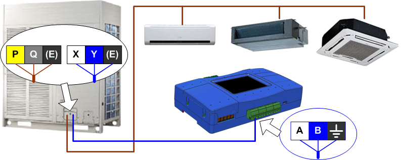
Connecting to Midea VRF system
- If CoolMasterNet is the only central controller in the system:

Outdoor Switch SW3-1 must be ON for proper operation of CoolMasterNet connected to XYE bus.
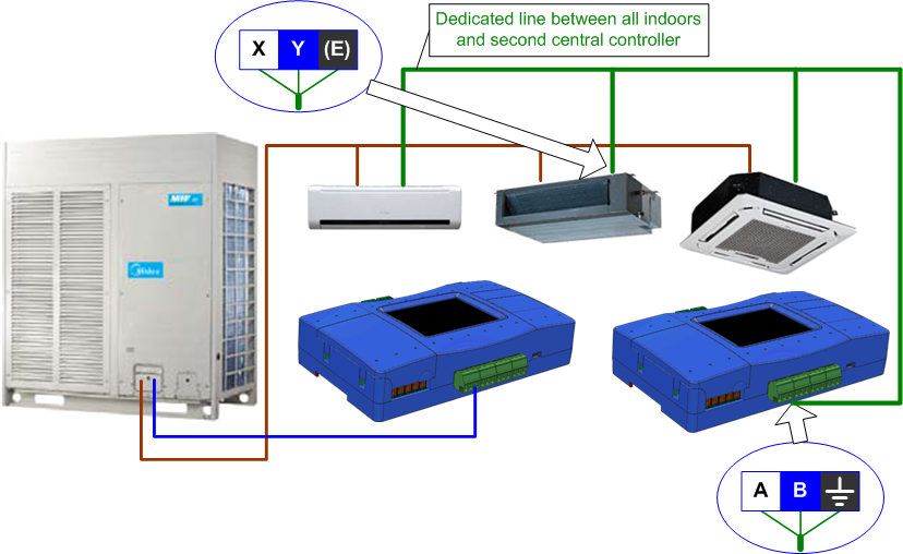
- If two central controllers should be connected:
We recommend to connect to line L7 on CoolMasterNet. Lines L4, L5, L6 can also be used.
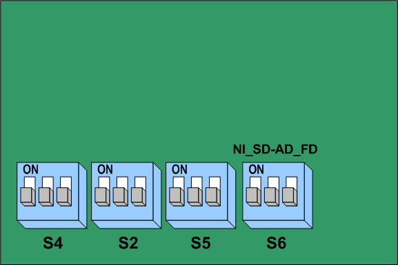
Auto Addressing Mode
For proper operation of the Central Controller (CoolMasterNet), it is important to have an Auto Addressing Mode turned ON on Outdoor PCB. This is done by setting S6 (on some models it is called NI_SD-AD_FD) DIP Switches to OFF-OFF-OFF positions like shown on the below picture. After that setting is done it is required to power reset the Outdoor unit.

Midea VRF Error Codes
| Malfunction Code | Problem Description |
Cool Automation Encoding | |
|---|---|---|---|
| HEX | DEC | ||
| E0 | Phase sequence disorder or loss of power phase | 0x10 | 16 |
| E1 | Communication malfunction | 0x11 | 17 |
| E2 | T1 sensor malfunction | 0x12 | 18 |
| E3 | T2A sensor malfunction | 0x13 | 19 |
| E4 | T2B sensor malfunction | 0x14 | 20 |
| E5 | T3 or T4 sensor of discharge of compressor fails down | 0x15 | 21 |
| E6 | Detection of current direction alternating is abnormal | 0x16 | 22 |
| E7 | EEPROM error | 0x17 | 23 |
| E8 | Fan speed is out of control | 0x18 | 24 |
| E9 | Communication malfunction between main board and display board | 0x19 | 25 |
| EA | Compressor Over-current (four times) | 0x1A | 26 |
| EB | Inverter module protection | 0x1B | 27 |
| EC | Cleaning malfunction | 0x1C | 28 |
| ED | Outdoor unit malfunction | 0x1D | 29 |
| EE | Water level detection malfunction | 0x1E | 30 |
| EF | Other malfunctions | 0x1F | 31 |
| P0 | Evaporator temperature protection | 0x20 | 32 |
| P1 | Anti-cool or defrost protection | 0x21 | 33 |
| P2 | Condenser high-temperature protection | 0x22 | 34 |
| P3 | Compressor temperature protection | 0x23 | 35 |
| P4 | Discharge pipe temperature protection | 0x24 | 36 |
| P5 | Discharge high pressure protection | 0x25 | 37 |
| P6 | Discharge low pressure protection | 0x26 | 38 |
| P7 | Voltage of power supply is too high or too low protection | 0x27 | 39 |
| P8 | Compressor over-current protection | 0x28 | 40 |
| P9 | Reserved | 0x29 | 41 |
| PA | 0x2A | 42 | |
| PB | 0x2B | 43 | |
| PC | 0x2C | 44 | |
| PD | 0x2D | 45 | |
| PE | 0x2E | 46 | |
| PF | 0x2F | 47 | |
| 00# | Communication malfunction between NIM and main PCB | 0x30 | 48 |
| 01# | Communication malfunction between central controller and NIM | 0x31 | 49 |
| 02# | Communication malfunction between central controller and functional module | 0x32 | 50 |
| 03# | Communication malfunction between central controller and PC (gateway) | 0x33 | 51 |
| 04# | Control Operation denied | 0x34 | 52 |
| 05# | Control Operation timeout | 0x35 | 53 |
| 06# | Address does not exist | 0x36 | 54 |
| 07# | Unsupported Control Operation | 0x37 | 55 |
